\n
## Diagram: State Transition Diagram
### Overview
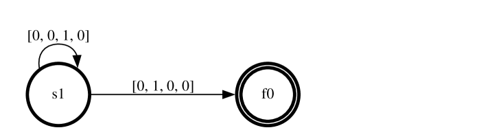
The image depicts a state transition diagram with two states: 's1' and 'f0'. Arrows indicate transitions between these states, labeled with numerical vectors. The diagram appears to represent a finite state machine or a similar system where the state changes based on input or events.
### Components/Axes
The diagram consists of:
* **States:** 's1' (left) and 'f0' (right).
* **Transitions:** Two labeled arrows.
* **Labels:** Numerical vectors associated with each transition.
### Detailed Analysis or Content Details
* **State 's1':** A circular node labeled "s1". It has a self-looping transition.
* **Self-loop Transition:** Labeled with the vector "[0, 0, 1, 0]". This indicates that when in state 's1', a transition back to 's1' occurs with the specified input.
* **State 'f0':** A circular node labeled "f0". It has a self-looping transition.
* **Self-loop Transition:** The state 'f0' has a self-looping transition.
* **Transition from 's1' to 'f0':** An arrow pointing from 's1' to 'f0', labeled with the vector "[0, 1, 0, 0]". This indicates a transition from state 's1' to state 'f0' occurs with the specified input.
### Key Observations
The diagram shows a system that can be in either state 's1' or 'f0'. State 's1' can return to itself, and can also transition to 'f0'. State 'f0' can only return to itself. The vectors associated with the transitions likely represent input conditions or events that trigger the state changes.
### Interpretation
This diagram likely represents a simple finite state machine. The states 's1' and 'f0' could represent different modes of operation or stages in a process. The vectors "[0, 0, 1, 0]", "[0, 1, 0, 0]" represent the conditions that cause the transitions between states. The self-loop on 'f0' suggests that once the system enters state 'f0', it remains there unless a different, unrepresented input causes a transition. The diagram is a concise way to visualize the possible states and transitions of a system, making it useful for design, analysis, and documentation. The vectors suggest a 4-dimensional input space, where each element of the vector represents a binary condition (0 or 1).