## Diagram: Bidirectional Transformation Between Two Structures
### Overview
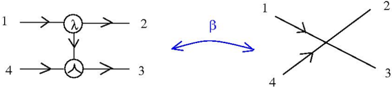
The image depicts a bidirectional relationship (labeled **β**) between two distinct diagrammatic structures. The left structure consists of a directed graph with labeled nodes and symbolic operations, while the right structure shows intersecting lines with numerical labels. The bidirectional arrow **β** suggests equivalence, transformation, or duality between the two systems.
---
### Components/Axes
1. **Left Diagram**:
- **Nodes**:
- Node **1** (top-left) → Node **2** (top-right) via a directed arrow.
- Node **4** (bottom-left) → Node **3** (bottom-right) via a directed arrow.
- **Symbols**:
- Node **1** contains the symbol **λ** (lambda).
- Node **4** contains a triangular symbol (△).
- **Flow**: Arrows indicate directional relationships (1→2, 4→3).
2. **Right Diagram**:
- **Lines**: Two intersecting lines labeled **1**, **2**, **3**, **4** (clockwise from top-left).
- **Arrows**: Bidirectional arrows on the intersecting lines, suggesting mutual interaction or transformation.
3. **Bidirectional Relationship**:
- **β**: A curved double-headed arrow connecting the left and right diagrams, labeled **β** (beta).
---
### Detailed Analysis
- **Left Diagram**:
- The symbols **λ** and **△** likely represent specific operations or transformations applied to nodes 1 and 4, respectively.
- The directed arrows (1→2, 4→3) imply a sequential or causal relationship between nodes.
- **Right Diagram**:
- The intersecting lines labeled **1–4** may represent a transformed or equivalent state of the left diagram’s nodes, with the crossing points indicating interactions or dependencies.
- **β Relationship**:
- The bidirectional arrow **β** implies a reversible or symmetric relationship between the two structures. This could denote:
- A mathematical equivalence (e.g., isomorphism).
- A process transformation (e.g., input-output mapping).
- A duality in system behavior.
---
### Key Observations
1. **Symbolic Operations**: The use of **λ** and **△** suggests specialized functions or rules governing the left diagram’s nodes.
2. **Structural Equivalence**: The right diagram’s intersecting lines mirror the left diagram’s node connections, hinting at a transformed or abstracted representation.
3. **Bidirectional Flow**: The **β** arrow emphasizes reciprocity, suggesting the relationship is not unidirectional.
---
### Interpretation
This diagram likely illustrates a conceptual or mathematical framework where:
- The left structure represents a **source system** with explicit operations (**λ**, **△**) and directional dependencies.
- The right structure represents a **transformed system** where interactions are abstracted into intersecting lines, possibly simplifying or generalizing the original relationships.
- The **β** relationship bridges these systems, indicating they are equivalent under certain conditions (e.g., a homomorphism, duality, or isomorphism).
The absence of numerical data or explicit units suggests this is a **conceptual diagram** rather than an empirical chart. The focus is on illustrating relationships, transformations, or equivalences between two abstract systems.