## Diagram: Signal Reception Model with Feasible/Infeasible Regions
### Overview
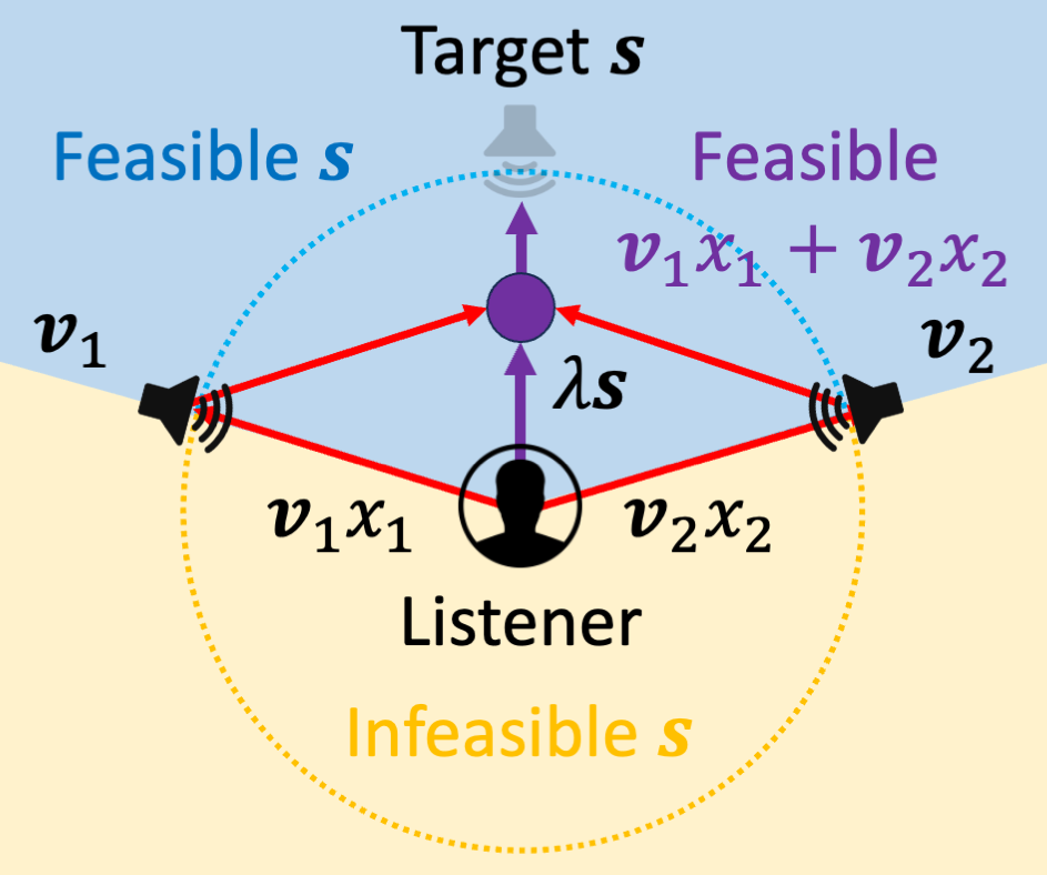
The diagram illustrates a signal reception system involving a listener, two speakers, and a target signal. It distinguishes between "Feasible" and "Infeasible" signal regions using geometric and mathematical notation. The central listener receives signals from two speakers, with mathematical expressions defining signal combinations and constraints.
### Components/Axes
- **Central Elements**:
- **Listener**: Represented by a human silhouette at the center.
- **Target Signal (s)**: Labeled "Target s" at the top, depicted as a speaker emitting waves.
- **Feasible Region**: Blue dotted circle labeled "Feasible s" encompassing the listener.
- **Infeasible Region**: Yellow dotted area outside the blue circle, labeled "Infeasible s."
- **Speakers**:
- **Speaker 1 (v₁)**: Left side, emitting red arrows labeled **v₁x₁**.
- **Speaker 2 (v₂)**: Right side, emitting red arrows labeled **v₂x₂**.
- **Mathematical Notations**:
- **Feasible Signal Combination**: Purple text "Feasible" with equation **v₁x₁ + v₂x₂**.
- **Scaling Factor**: Purple arrow labeled **λs** pointing from the listener to the target signal.
- **Color Coding**:
- **Blue**: Feasible s (dotted circle boundary).
- **Purple**: Feasible region and target signal.
- **Red**: Signal paths from speakers to listener.
- **Yellow**: Infeasible s (outer dotted boundary).
### Detailed Analysis
1. **Signal Paths**:
- Red arrows from speakers (v₁ and v₂) converge at the listener, representing signal transmission.
- The feasible region (blue) is bounded by **v₁x₁ + v₂x₂**, suggesting combined signals from both speakers define the feasible zone.
2. **Target Signal**:
- The target signal **s** is positioned above the feasible region, with a purple arrow (**λs**) indicating its relationship to the listener’s reception capabilities.
3. **Regions**:
- **Feasible s**: Signals within the blue circle are deemed "Feasible," likely representing acceptable or decodable signals.
- **Infeasible s**: Signals outside the yellow dotted boundary are "Infeasible," possibly too weak or distorted for reliable reception.
4. **Variables**:
- **v₁, v₂**: Likely represent signal strength or modulation parameters for each speaker.
- **x₁, x₂**: Could denote time/frequency indices or spatial coordinates for signal components.
- **λs**: A scaling factor modulating the target signal’s strength or relevance.
### Key Observations
- The feasible region is circular, centered on the listener, implying symmetric reception capabilities.
- The target signal **s** is positioned at the edge of the feasible region, suggesting it is the boundary condition for optimal reception.
- The infeasible region expands outward from the feasible circle, indicating diminishing signal quality with distance.
### Interpretation
This diagram models a communication system where:
- **Signal Combination**: The listener’s ability to decode signals depends on the sum of contributions from two speakers (**v₁x₁ + v₂x₂**).
- **Feasibility Constraints**: Only signals within the blue feasible region (bounded by **λs**) are considered viable for processing.
- **Target Signal Role**: The target **s** acts as a reference or desired signal, with its strength scaled by **λs** to determine feasibility.
The model emphasizes trade-offs between signal strength (v₁, v₂), spatial positioning, and reception thresholds (λs). The infeasible region highlights limitations in signal propagation or environmental interference. The use of geometric boundaries (circles) suggests a simplified physical or mathematical model of signal coverage.