\n
## Diagram: U-Net Architecture Visualization
### Overview
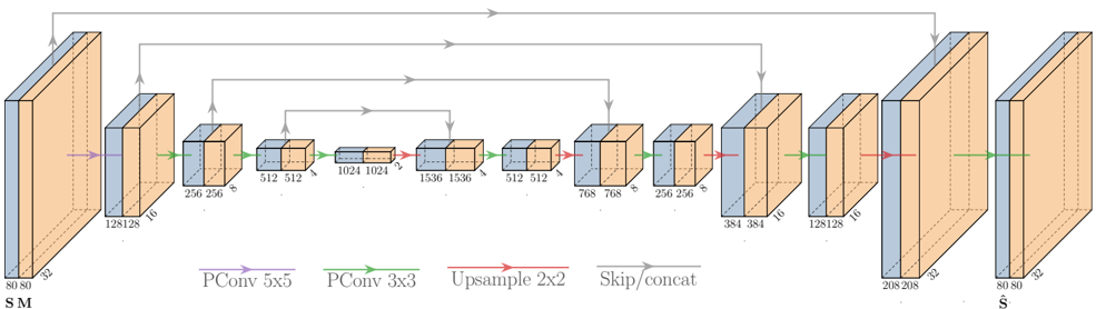
The image depicts a simplified U-Net architecture, a common convolutional neural network used for image segmentation. The diagram illustrates the encoder-decoder structure with skip connections. The flow of data is generally left-to-right, with a contracting path (encoder) on the left and an expanding path (decoder) on the right. The diagram uses 3D blocks to represent layers or groups of layers, with dimensions indicated on each block.
### Components/Axes
The diagram uses the following visual cues:
* **Rectangular Blocks:** Represent layers or groups of convolutional layers. Dimensions (width x height x depth) are labeled on each block.
* **Arrows:** Indicate the flow of data.
* **Color-coded Lines:** Represent different types of operations:
* **Green:** PConv 5x5 (presumably a convolutional layer with a 5x5 kernel)
* **Teal:** PConv 3x3 (presumably a convolutional layer with a 3x3 kernel)
* **Red:** Upsample 2x2 (upsampling operation, likely bilinear interpolation)
* **Purple:** Skip/concat (skip connection, concatenating feature maps)
* **Labels:** "SM" (likely input image), "Ŝ" (likely output segmented image).
### Detailed Analysis or Content Details
The diagram can be broken down into sections:
**Encoder (Left Side):**
1. **Input:** 80x80x3 (labeled "SM")
2. **Layer 1:** 128x128x16 (Green PConv 5x5)
3. **Layer 2:** 256x256x16 (Teal PConv 3x3)
4. **Layer 3:** 512x512x32 (Teal PConv 3x3)
5. **Layer 4:** 1024x1024x64 (Teal PConv 3x3)
6. **Layer 5:** 1536x1536x128 (Teal PConv 3x3)
**Bottleneck (Center):**
7. **Layer 6:** 512x512x128 (Teal PConv 3x3)
8. **Layer 7:** 768x768x64 (Teal PConv 3x3)
**Decoder (Right Side):**
9. **Layer 8:** 256x256x32 (Red Upsample 2x2, Purple Skip/concat from Layer 5)
10. **Layer 9:** 384x384x16 (Teal PConv 3x3)
11. **Layer 10:** 128x128x16 (Red Upsample 2x2, Purple Skip/concat from Layer 3)
12. **Layer 11:** 208x208x32 (Teal PConv 3x3)
13. **Layer 12:** 80x80x32 (Red Upsample 2x2, Purple Skip/concat from Layer 1)
14. **Output:** 80x80x32 (labeled "Ŝ")
The skip connections are indicated by purple lines, connecting the output of a layer in the encoder to the input of a corresponding layer in the decoder. These connections concatenate the feature maps from the encoder and decoder.
### Key Observations
* The architecture follows a U-shape, with a contracting path (encoder) and an expanding path (decoder).
* The number of feature channels increases in the encoder and decreases in the decoder.
* Skip connections are used to preserve fine-grained details from the encoder during the decoding process.
* The dimensions of the blocks change systematically, reflecting the downsampling and upsampling operations.
### Interpretation
This diagram illustrates the core principles of the U-Net architecture. The encoder extracts hierarchical features from the input image, while the decoder reconstructs the segmented image from these features. The skip connections are crucial for preserving spatial information and improving segmentation accuracy. The U-Net is particularly effective for image segmentation tasks where precise localization of objects is important. The use of different convolutional kernel sizes (5x5 and 3x3) suggests an attempt to capture both broad contextual information and fine-grained details. The increasing and decreasing number of feature channels reflects the trade-off between representational capacity and computational cost. The diagram provides a high-level overview of the architecture and does not include details about activation functions, normalization layers, or other implementation specifics.