## Room Setup Photographs
### Overview
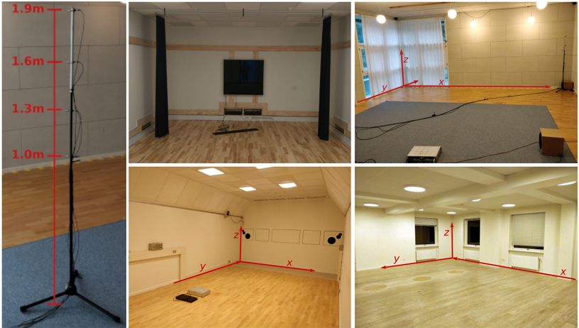
The image presents a series of photographs depicting different room setups, likely for acoustic measurements or experiments. The photos showcase various room configurations, equipment placements, and coordinate axes.
### Components/Axes
* **Photo 1 (Top Left):** Shows a microphone stand with height markers.
* Height markers (from bottom to top): 1.0m, 1.3m, 1.6m, 1.9m.
* **Photo 2 (Top Middle):** Shows a room with a TV screen, wooden paneling, and black acoustic panels.
* **Photo 3 (Top Right):** Shows a room with a carpeted area, windows with curtains, and coordinate axes.
* Coordinate axes: x, y, z.
* **Photo 4 (Bottom Left):** Shows a room with acoustic treatment panels on the wall and coordinate axes.
* Coordinate axes: x, y, z.
* **Photo 5 (Bottom Right):** Shows a room with windows and coordinate axes.
* Coordinate axes: x, y, z.
### Detailed Analysis
* **Microphone Stand (Photo 1):** A black microphone stand is shown with red lines indicating specific heights. The heights are labeled as 1.0m, 1.3m, 1.6m, and 1.9m. The stand is placed on a blue carpet.
* **Room with TV (Photo 2):** The room features a large TV screen mounted on the wall, surrounded by wooden paneling. Two tall, black acoustic panels are positioned on either side of the TV. The floor is made of wooden planks.
* **Carpeted Room (Photo 3):** A room with a large gray carpet covering a portion of the floor. Windows with white curtains are visible. Red lines indicate the x, y, and z axes. A microphone stand is visible in the background.
* **Acoustically Treated Room (Photo 4):** The room has white walls with several square acoustic panels. Red lines indicate the x, y, and z axes. Some equipment is placed on the floor.
* **Room with Windows (Photo 5):** The room has windows with blinds. Red lines indicate the x, y, and z axes. The floor appears to be made of a light-colored material.
### Key Observations
* The microphone stand in Photo 1 is used as a reference for height measurements.
* Photos 3, 4, and 5 include coordinate axes (x, y, z), suggesting spatial measurements or acoustic analysis.
* The rooms in Photos 2 and 4 are treated with acoustic panels, indicating a focus on sound control.
### Interpretation
The images likely document different stages or setups of acoustic experiments or measurements in various rooms. The microphone stand provides a height reference, while the coordinate axes in other photos suggest spatial data collection. The presence of acoustic panels indicates a controlled environment for sound-related studies. The different room configurations may be used to analyze how room acoustics affect sound propagation and perception.