\n
## Photographs: Room Setup with Coordinate Systems
### Overview
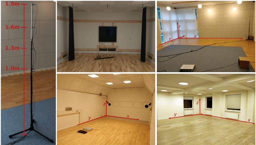
The image presents a collage of six photographs depicting interior views of what appears to be an acoustic testing room or similar controlled environment. Each photograph showcases a different perspective of the room, with five of the six images including a 3D coordinate system (x, y, z) overlaid on the scene. One image shows a microphone stand with height markings.
### Components/Axes
The coordinate systems consistently use the following:
* **x-axis:** Represented by a red line, generally oriented along the longer dimension of the room.
* **y-axis:** Represented by a red line, generally oriented along the shorter dimension of the room.
* **z-axis:** Represented by a red line, oriented vertically, indicating height.
The microphone stand image displays height markings in meters:
* 1.0 m
* 1.3 m
* 1.6 m
* 1.9 m
### Detailed Analysis or Content Details
**Image 1 (Top-Left):** Microphone stand. The stand is black and positioned on a blue carpet. The height markings are clearly visible along the vertical pole.
**Image 2 (Top-Center):** Room view with a television and sound absorption panels. The room has wooden flooring and black sound absorption panels on the walls. A television is mounted on the wall above a low cabinet.
**Image 3 (Top-Right):** Room view with a window and coordinate system. The room has a window covered with white curtains. The coordinate system is overlaid, with the x-axis extending along the length of the room, the y-axis along the width, and the z-axis vertically. A small device is placed on the floor near the origin of the coordinate system.
**Image 4 (Bottom-Left):** Room view with coordinate system and wall-mounted objects. The room has a light-colored wooden floor and light-colored walls. Several small, square objects are mounted on the wall. The coordinate system is overlaid, similar to Image 3. A small device is placed on the floor near the origin of the coordinate system.
**Image 5 (Bottom-Right):** Room view with a window, coordinate system, and furniture. The room has a window covered with a roller blind. A dark-colored cabinet is visible in the background. The coordinate system is overlaid, similar to Images 3 and 4.
### Key Observations
* The coordinate systems are consistently oriented, suggesting a standardized measurement approach within the room.
* The presence of sound absorption panels in Image 2 indicates the room is designed for acoustic measurements or controlled sound environments.
* The small devices placed near the origin of the coordinate systems in Images 3 and 4 likely represent measurement points or the location of a sound source.
* The varying room configurations suggest multiple testing setups or different acoustic conditions.
* The microphone stand in Image 1 indicates sound recording or analysis is performed.
### Interpretation
The images document a controlled environment designed for acoustic testing or research. The consistent use of a 3D coordinate system suggests precise spatial measurements are being taken. The presence of sound absorption materials and a microphone indicates the room is used for analyzing sound properties, potentially including sound pressure levels, reverberation time, or sound localization. The different room configurations suggest the ability to vary the acoustic environment for different experiments. The height markings on the microphone stand provide a reference for vertical positioning of the microphone during measurements. The images collectively demonstrate a systematic approach to acoustic analysis within a controlled setting. The images do not provide any quantitative data beyond the height markings on the microphone stand.